Educational objectives
• Studying of the controlled, non-controlled and mixed rectification of the single-phase
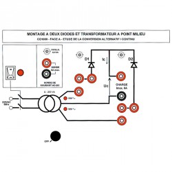
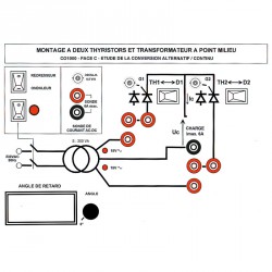
PANEL A: ASSEMBLY WITH TWO DIODES AND MID-POINT TRANSFORMER
Return to single half-wave rectification and switching to double half-wave rectification by simply adding jumper straps.
Experiment 1 Power flow on resistive load (R)
Experiment 2 Power flow on inductive load (R,L)
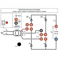
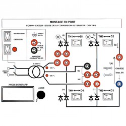
PANEL B: DIODE BRIDGE CIRCUIT ASSEMBLY
Experiment 1 Power flow on resistive load (R)
Experiment 2 Power flow on inductive load (R,L)
Experiment 3 Power flow on active load (E,R)
Experiment 4 Power flow on active inductive load (E,R,L)
Experiment 5 Application to a DC motor power supply
Any of these 4 diodes can be replaced by a rectifier at any time, simply by throwing the appropriate switch. This facilitates comparisons between all-diode, all-rectifier, symmetrical mixed, and asymmetrical mixed assemblies.
PANEL C: ASSEMBLY WITH TWO RECTIFIERS AND MID-POINT TRANSFORMER
Controlled single- and double-wave rectification.
The tests on panel A may be used again for comparison.
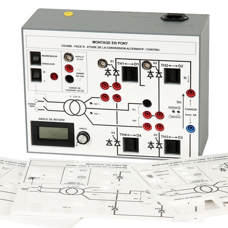
PANEL D: BRIDGE CIRCUIT ASSEMBLY (ALL RECTIFIERS OR MIXED)
Comparative studies of diode / rectifier / mixed assemblies
Experiment 1 Power flow on active inductive load (E, R, L)
Operates as a static convertor
Operates as a grid-interactive inverter
Experiment 2 Application to a DC motor power supply (DCM)
Mixed bridge-circuit assembly
Experiment 3 Power flow on active inductive load (E, R, L)
Experiment 4 Application to a DC motor power supply (DCM)
Educational objectives
• Studying of the controlled, non-controlled and mixed rectification of the single-phase
Free
quotation
Answer
under 48H00
Belgium
Delivery
2 years warranty
for all our products
Export service
available