Educational objectives
• To learn about the notion of electrical hazard (qualitatively and quantitatively).
• To demonstrate the features of each earthing connection scheme (TT, TN, IT)
• To be able to explain the role of each element of the protective arrangements (earthing connection, thermal magnetic circuit-breaker, residual current device, IMD).
• To show the fault current paths without danger.
• To take into account standard NFC 15-100
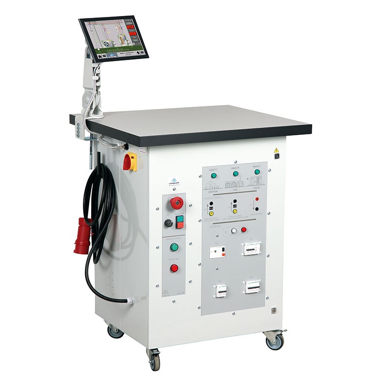
SLT is a teaching system covering the main elements employed in protection against the electrical hazards of indirect or direct contact (residual current devices with several sensitivities, thermal magnetic circuit-breakers, three-phase transformer). It demonstrates the principle of electrical protective devices in TN, TT and IT earthing connection schemes. The teaching sequences are organized so as to discover the restrictions, outcomes and adjustments required for good protection against electrical hazards.
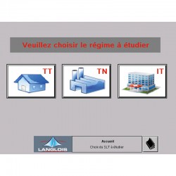
Use of the system and running the tests are clearly guided by means of an HMI with touchscreen. The student has no cabling to create as the connections are transparently controlled by relaying. The student can thus concentrate on understanding the phenomena. Using the touchscreen, the student can select the type of neutral system to be studied, the different resistance values of faults, earthing and the human body, see the equipotential bonding, visualize the leakage current, simulate a fault and produce the insulation fault without danger.
Each test is linked to a clear synoptic diagram, displayed on screen. Voluntary action on the HMI displays the potentials at the different points of the installation, as well as the path of the fault current and its intensity. The indicated values result from different case simulations:
- with or without insulation fault,
- with or without contact
- before or after protective device tripping.
The student validates the results of the simulation (and its calculations) by performing a test to see a protective device trip or not, and to measure the contact voltage and fault current with measuring instruments (not supplied).
Comprises
• Electrical cabinet on casters with worktop.
• 1 PVC panel equipped with emergency stop button, Start/Stop button and 2 Operation + Fault indicator lights.
• 1 PVC panel equipped with:
- diagram with 3 indicator lights for visualizing the selected neutral system.
- 4 safety terminals 4mm for reading the contact voltage between the earth and body as well as between the earth and a second body. 2 additional terminals 4mm for reading the fault current.
- an insulation monitoring device (IMD).
- a set of circuit-breakers and residual current devices used in each earthing connection scheme.
• 1 programmable logic controller (PLC) M221 (inside the cabinet) for managing all the functionalities.
• HMI 7.5", colour + support arm (ref. SLT-1-T8W only).
Educational objectives
• To learn about the notion of electrical hazard (qualitatively and quantitatively).
• To demonstrate the features of each earthing connection scheme (TT, TN, IT)
• To be able to explain the role of each element of the protective arrangements (earthing connection, thermal magnetic circuit-breaker, residual current device, IMD).
• To show the fault current paths without danger.
• To take into account standard NFC 15-100
Free
quotation
Answer
under 48H00
Belgium
Delivery
2 years warranty
for all our products
Export service
available